FSD115-Element Safety Functions
See this document (FSD115-Element Safety Functions). |
Overview
To be able to identify and specify the element safety functions, a system overview description is needed.
System overview
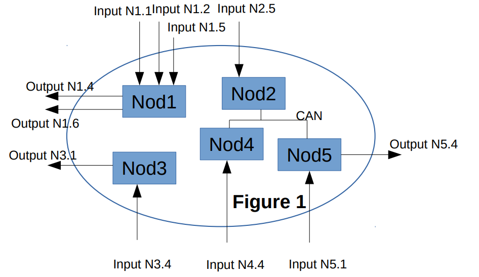
The Safety Simplifier System consists of one or more (up to 16) nodes that communicate with each other via radio and/or CAN communication.
Figure 1 shows an example.
In Figure 1, all nodes, CAN and radio together sums up to the System Logic.
Inputs and outputs are always electrical signals on the terminals. Ie, from a system point of view, the radio and CAN cannot be input or outputs to other systems.
System logic consists of all node logic, together with radio and CAN communication.
Node overview
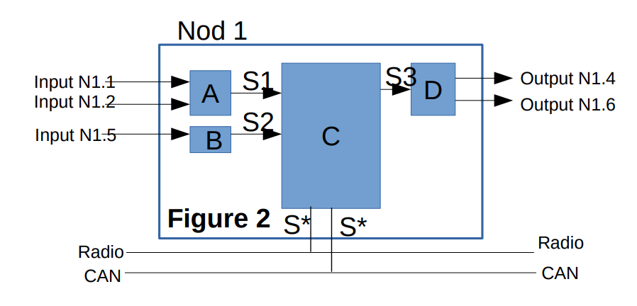
In Figure 2, a specific node is analyzed. From the node perspective, there can be both electrical inputs, and communication via radio and CAN and CAN can both be inputs and outputs.
Likewise, for outputs, they can be both electrical and communication.
Node logic consists of the CPUs with electronics that handles the node inputs, and generates the node outputs.
System Summary
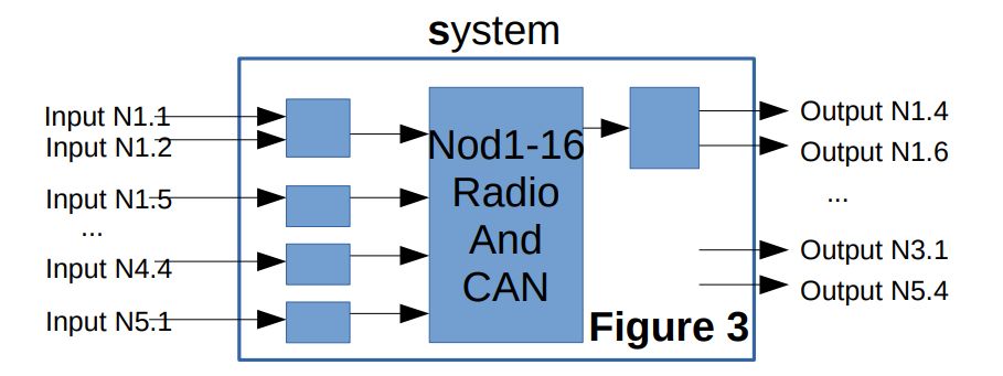
From a functional specification, Figure 1 can be redrawn as Figure 3. In Figure 3, the system logic in the middle is clearly shown, in respect to the inputs and outputs.
In both Figure 2 and Figures 3, there are elements that convert to/from physical I/Os to logical signals. A common example is that a redundant input generates a single signal (ie, Input N1.1/N1.2 => “A” => signal S1).
A signal is always On or Off, ie digital. The physical I/O(s) that matches the logical signal states is quite freely configured.
System IO specifications
See document FSD210 for a detailed overview of the different types of inputs and outputs.
Element Safety Functions
As the Simplifier is a general, configurable unit, the Element Safety Functions also becomes general.
There are two main output types. Transistor outputs and Relay outputs. The safety functions are defined by these.
Element Safety Function 1 - Signal guarantee
Consider a system with inputs (see figure 3), that generates a signal that controls output(s). Under the assumption that the logic fulfils below requirements, then if the logic is configured to turn off the output signal under certain conditions, we guarantee that this happens if the input signals meet the off condition(s).
Notes:
We cannot guarantee to generate an ON signal under all circumstances. Power loss is a simple example of this.
This Element Safety Function (ESF) is defined by signals. For a complete system, it needs to be combined with ESF*
Logic requirements:
The logic chain must not have an internal signal where its OFF state would turn on the output
Element Safety Function 2 - Redundant inputs
For physical inputs, they are converted to internal signals according to I/O types (see FSD210) and the input block.
For redundant (at least two) physical inputs or information redundancy (dynamic signal see FSD210), ESF2 will guarantee an internal OFF signal if the input signals have a state that corresponds to this, except for configurations where all physical inputs are OFF would give an internal ON signal.
Element Safety Function 3 - Redundant outputs
For physical outputs, internal signals are converted to output signals from the system logic, transistor outputs or relay outputs. In each output there shall be redundant transistors/relays.
Figures
Hardware Elements
The user have 14 accessible connections on the Safety simplifier unit terminal block and which are individually configurable as either inputs- or outputs. All connections configured as outputs has a common supply in accordance to Figure 1 which also is controllable by the Safety Simplifier unit.
In addition, the user also have up to 2 accessible and potential free relay outputs, individually operating in 1oo2 configuration. Thus, five hardware elements were identified: 1. Input element 2. Logic element 3. Single transistor output element 4. Double transistor output element 5. Relay output element

Figure 1: Safety Simplifier reference architecture
One Safety Simplifier unit may be used as part in the implementation of one or several safety functions (as limited by the amount of inputs and outputs in the actual system configuration). Thus, the overall achievement of SIL must be evaluated for each implemented safety function individually. As a subsystem the Safety Simplifier unit may be used according to the following configurations, for each specific safety function:
The following configurations are defined:
1. The Safety Simplifier together with external components (sensors and output devices) forma a single SRP/CS implementing a safety function according to ISO 13849-1 with the potential of fulfilling category 4. The resulting safety integrity has to be evaluated for each specific application with respect to specific reliability data of external components and the techniques applied for monitoring/diagnostics (m) together with the results of this report.
2. The Safety Simplifier implements a safety function as a subsystem in combination with at least one other and external subsystem (either as input or output). The external subsystem has to be interconnected to the Safety Simplifier by compatible means in order to maintain its SIL, either by: - Comparison of the external subsystem safety manual (if available) and the Safety Simplifier safety manual, or - Conducting a separate and detailed analysis of the external subsystem and its interconnections with respect to the Safety Simplifier safety manual.
3. A Safety Simplifier unit is interconnected to (n) other Safety Simplifier units using their provided data communication interfaces (CAN-bus or radio).
4. The relay outputs of the Safety Simplifier are used as power control elements, i.e. O1 and O2 are fully integrated including their respective monitoring. The LOAD is typically the power supply of another subsystem that conforms to either IEC 61508 or ISO 13849-1.
Revision History
Date |
By |
Version |
Description |
2017-02-23 |
Mats Linger |
V1 |
Initial version |
2025-07-28 |
Jesper Ribbe |
V2 |
Incoporated details from previous Hardware Evaluation (section Hardware Elements). Added UART configuration, clarified power supply. Corrected input as 1oo2. |